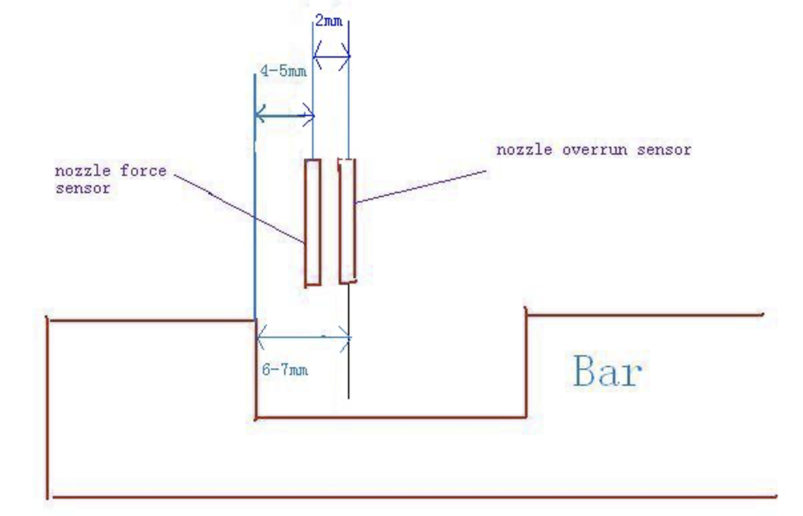
This guide provides step-by-step instructions for adjusting the nozzle force sensor to ensure accurate operation and prevent material leakage. Start by identifying the nozzle force sensor and nozzle overrun sensor. You can confirm the nozzle force sensor by observing the light at the back of the sensor when the nozzle touches the mold, or by checking for the "Nozzle Touch Check" indicator when the sensor contacts the bar. Once identified, set the nozzle force sensor distance to 4-5mm, a value optimized through software testing. Ensure the nozzle overrun sensor maintains a minimum distance of 2mm. Adjustments should be finalized to prevent material from escaping the nozzle, completing the setup.
To adjust the sensor
First, you must make sure the one is nozzle force sensor,and the other is nozzle overrun sensor.
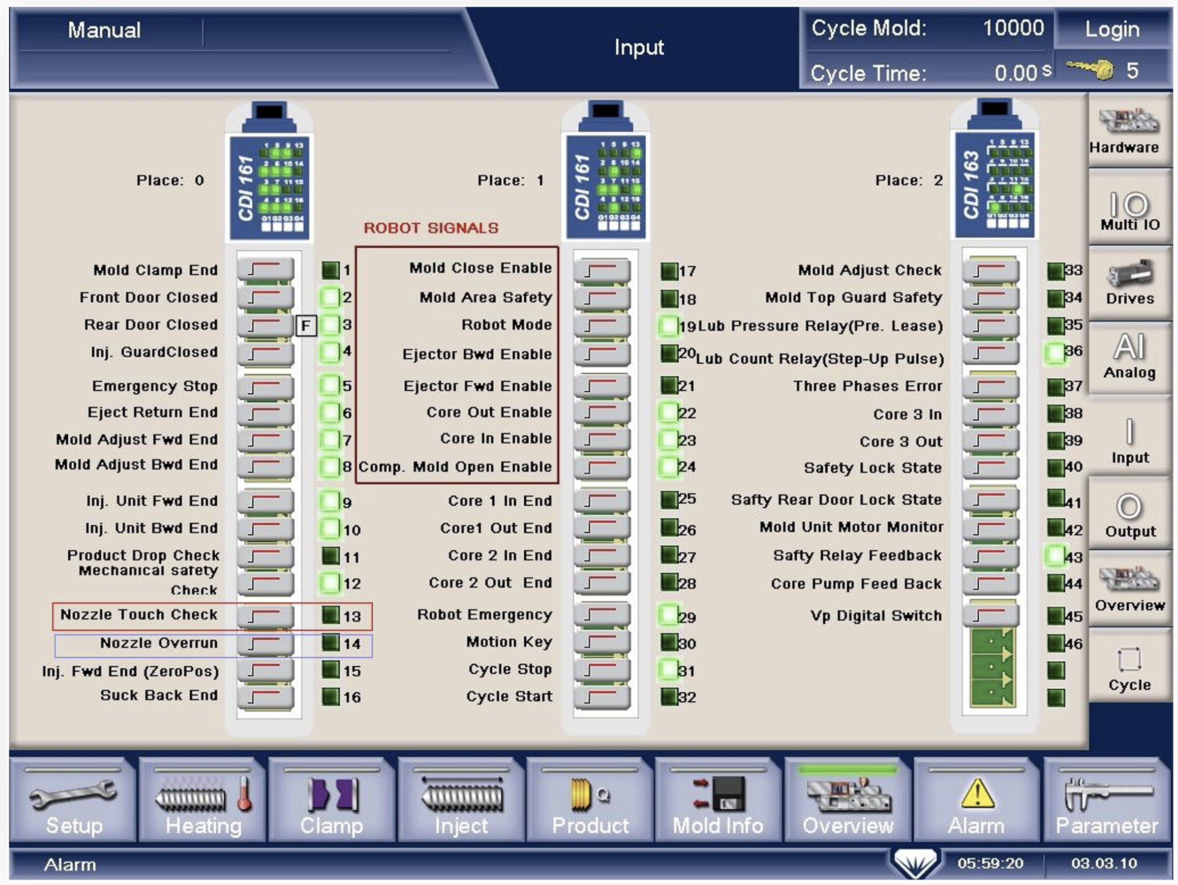
You can see the light in the back of sensor when the nozzle touch the mould ,if the light is on, it is the nozzle force sensor.
You also see the light when you let the sensor touch the bar, if you see the "Nozzle Touch Check" is on, it is the nozzle force sensor.
Second, after you make sure the sensors, you can see the picture I have draw.Maybe you will ask me why the distance is between 4 to 5mm?I only can tell you that we find the distance by the software. The distance of nozzle overrun sensor is more than 2mm.You just make sure the material not run out from the nozzle ,The work is finished.